

Imaging artifacts refer to something/error in the image that doesn’t indicate a true structure. Not all artifacts are bad. Some may be useful. “For example, the bright white ‘spike’ which occurs on the Doppler spectrum often referred to as a ‘valve click’ is in reality an artifact caused by circuit saturation. It is a useful artifact when controlled since it helps to quickly identify timing in the cardiac cycle (Miele, Ultrasound Physics & Intrumentation ).”
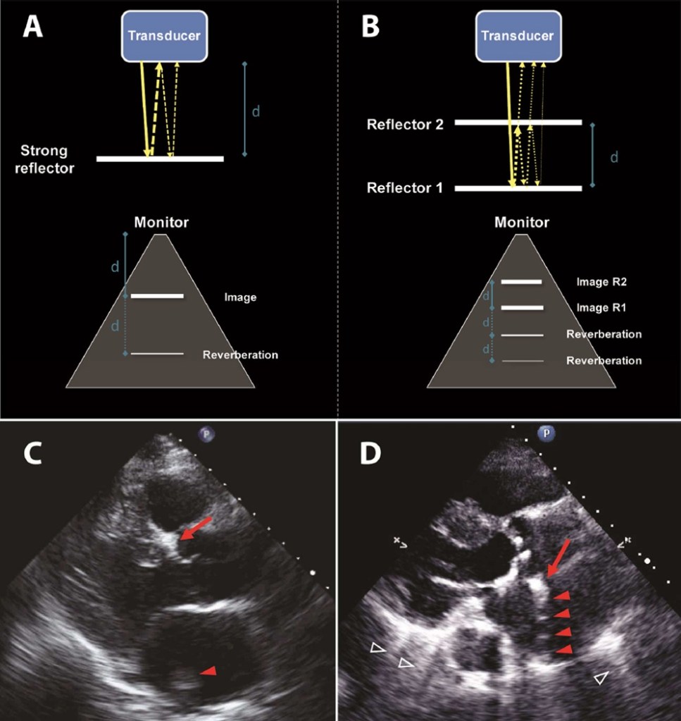
Table 1. Speed of Sound Through Tissues
Tissue Speed (m/s)
Air 330
Lung 604
Fat 1450
Soft tissue 1540
Blood 1570
Bone 4080
Table 2. Definitions in Ultrasound
Acoustic impedance It is determined by the tissue density multiplied by the
velocity of sound waves in the tissue. Differences in
acoustic impedance cause reflections (echoes).
Absorption The conversion of sound energy to heat as it travels
through a medium.
Attenuation The gradual loss of ultrasound energy as the wave
propagates through tissue; it is caused by reflection,
scattering, and absorption.
B-mode Brightness mode, which is most commonly referred to as
2D grayscale mode.
Reflection The redirection of a transmitted sound wave, usually at
an interface between 2 media with different acoustic
impedance.
Refraction The change of propagation direction (bending) of
ultrasound wave as it travels through media with
different propagation speeds. This can only occur
when the incident angle is different from 90°.
Scattering The reflected echoes propagate at various directions; it
occurs when the reflector has a small surface (i.e.,
red blood cells).
Here are the most common types of artifacts in ultrasound:
Spectral and Color Flow Doppler Artifacts
1. Aliasing – “Wrap-around” of the velocity scale. How to eliminate: Decrease the transmitted ultrasound frequency and/or the sector depth while maximizing scale or shifting the baseline.
2. Blooming – CFD velocities extend beyond the region of true blood flow. How to eliminate: Reduce gain setting.
3 . Spectral Doppler mirroring – Duplicate of Doppler spectrum above and below
the baseline. How to eliminate: Reduce the gain or power output or reposition the probe so that
Doppler angle is as close to 0 or 180° as possible.
4. Pseudoflow – Motion of fluid other than blood. How to eliminate: Spectral imaging will not show characteristic arterial or venous waveform.
5. Twinkling – Mosaic of rapidly changing blue and red patches of color near strongly reflective, surfaces. How to eliminate: Spectral Doppler of this artifact will produce a pattern consistent
with noise.
- Suboptimal image quality – which is done by poor tissue penetration due to body habitus like obesity or lungs disease or any type of post cardiac surgery. In order to improve image quality in echocardiography, one would need to have a TEE imagine done for a better diagnosis.
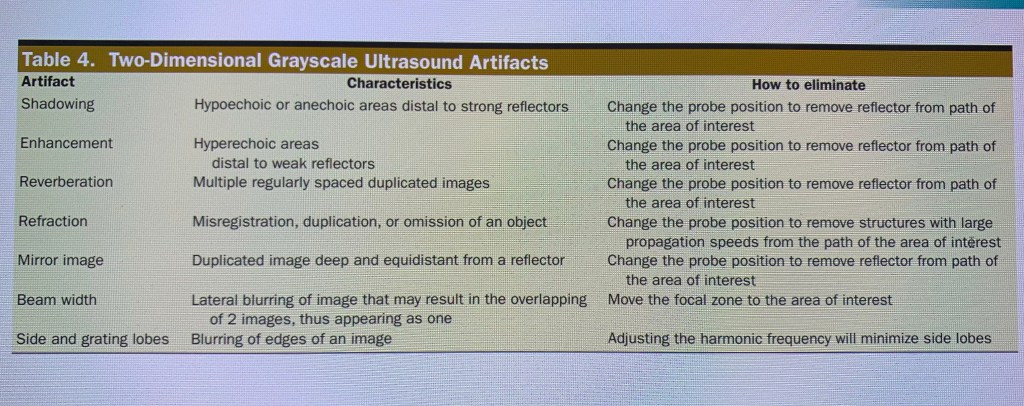
- Acoustic Shadowing – is a reflection of the ultrasound signal by a strong specular reflector for example, a prosthetic valve. It means that it will block the transmission of the wave, and no signal penetrates beyond the shadowing structure. The shadow looks like a light shadow.
- Reverberations – happens between two strong parallel reflectors causing parallel dense lines extending from the structure into the the far field. It makes hard to evaluate structures in the far field because of that. “In the parasternal long axis view, a linear echo in the aortic root that originates as a reverberation from anterior structures like ribs may be mistakes for a dissection flap.” (Otto, Textbook of Clinical Echocardiography).
- Beam width – it’s a superimposition of structures within the beam profile including side lobes into a single image.
- Lateral Resolution – happens at different imaging depth, and it’s a point which appears as a line and it’s length depends on depth and the amplitude of reflected signal. For example, a calcified mass or prosthetic valve that can appear longer than it is because of poor lateral resolution.
- Refraction – it’s a deviation of the wave from a straight path along the scan line. The wave passes through a tissue near the transducer causing it to be refracted. Often seen in parasternal short axis views of aortic valve, where a second valve can be seen partially overlapping the actual valve.
- Range ambiguity – occurs when echo signals from an earlier pulse cycle reach the transducer on the next ‘listen cycle’ for that scan line which results in deep structures appear closer to the transducer than they actually are (Otto, Textbook of Clinical Echocardiography).
- Electronic processing – it’s instrument specific.
- Ring down and comet Tail – when sound reverberate through air sac, the air sac is redrawn multiple times which creates a bright tail like structure that looks like comet. It can happen when there’s a calcific structure or a metallic structure such as mechanical valve.
- Multi-path – incorrectly displayed the depth of a structure caused by insonification of a specular reflector at an oblique angle. It makes the reflection to be redirected elsewhere.
- Side lobe and granting lobe – blurring of the edges artifact that can cause to create a duplicate image. The waves created from each of the elements are never completely out of phase off-axis of the main beam. The result is that energy propagates in undesired direction, returning echoes from undesired locations. (Miele, Ultrasound Physics & Intrumentation ).
- Speed error – if the propagation velocity is different at any time within the wave path, then the system will display an incorrect depth of a structure. Propagation velocity is 1540 m/s. If the propagation speed is higher than 1540 m/s, then echoes will return sooner and vice versa.
- Mirror artifact – it’s a mirrored image in an oblique incidence to a specular reflector. The specular reflection directs the reflected beam toward a structure and that structure is reflected by the specular reflector back to the transducer. Think of a diaphragm as an acoustic mirror.
- Shadowing – is an attenuation artifact and is caused by any form of attenuation that’s stronger than the surrounding area. for example, a gall stone is hyperechoic and can cause a shadowing to the nearest structure.
- Enhancement Artifact – enhancement is reciprocal of shadowing. So if a structure is a weaker reflector than normal then the beam is attenuated less than normal causing an enhancement towards the nearest structure. Usually happens when the beam passes through a structure filled with fluid like an artery or a cyst in a liver.
- Speckle – it’s a scattering from multiple structures in different directions.
- Aliasing – it’s a Doppler artifact – it happens when Nyquist limit is reached for PW Doppler and the sample rate is equivalent to PRF. Happens when there’s LVOT obstruction for example.

For more information on Ultrasound artifacts in echo please visit ASE website and https://www.asecho.org/wp-content/uploads/2021/01/Imaging_Artifacts_in_Echocardiography.11.pdf
also textbooks:
Otto, Textbook of Clinical Echocardiography
IMiele, Ultrasound Physics & Intrumentation
